
Full list
VRML Interactive Tutorial
Introduction
VRML File Structure
Drawing: Shape node
Geometry Nodes:
|
Box
Sphere Cone Cylinder PointSet IndexedLineSet IndexedFaceSet Extrusion ElevationGrid Example: Chessboard Text FontStyle |
| Material
Textures
Texture Transform |
|
Directional Light
Point Light Spot Light |
Hierarchical Node Structures
|
Group
Transform Collision Anchor Billboard Switch |
Defining and Instancing Nodes
Defining Levels of Detail
Events in VRML
|
Creating Paths between events:
ROUTE
Generating Events based on Timers or User Actions
|
|
Color
Coordinate Normal Orientation Position Scalar Example |
|
Sound
AudioClip |
|
Who Am I: NavigationInfo
Where Am I: ViewPoint |
|
Background
Fog |
| WorldInfo |
|
Coordinate
Color Normal |
Transform Node
The transform node is a grouping node. As a group node it can be used to define a set of nodes as a single object. However this is not the main purpose of this node. This node allows you to define a new local coordinate system for the nodes within the group.
This node can be used to perform the following geometric transformations:
All the nodes inside a Transform group are affected by these transformations, i.e. all coordinates are computed in the local coordinate system. Transform groups inside Transforms groups accumulate the transformations specified in each Transform. The inner Transform group defines a local coordinate system based on the coordinate system defined in the outer transform group.
The following fields are present:
Syntax:
|
Scale
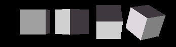
A scaling operation allows you to resize a shape. You can enlarge or decrease the size of a shape in any number of dimensions. The scale factors must be positive. The next figure presents an example.
The left box is a cube defined using the Box node without any scaling operation. The second is scaled in the X axis by 0.2, the third is scaled in the Y axis also by 0.2, and the fourth is scaled both in the Y and Z axes by 0.2.
Sometimes, you may wish that the axes to which the scaling operation is applied were not the standard axes. scaleOrientation field allows you to rotate the axes, the scaling factors will be applied to the rotated axes and not to the original axes. The scaleOrientation field specifies a vector which defines the rotation axis, and the angle measure for rotation.
The cube from the right had a scale of 1.3 in the Y axis which was previously rotated by 45 degrees in the Z axis. The next figure shows the computations involved step by step.
The left figure shows the axes and a box prior to any geometric transformations. The second shows the effect of the scaleOrientation, a rotation of 45 degrees in the Z axis. The scaleOrientation used was 0 0 1 0.75, the first three values specify a vector, the fourth an angle (recall that in VRML angles are defined in radians).
Note that after the third step the axes go back to normal, i.e. those in the left figure.
Because translation is the last transformation to be applied, it may sometimes be convenient to define a translated set of axes for the scaling operation. Note that as for the scaleOrientation, this translation is only effective for the scale transformation. The field center allows you to perform such a translation.
The next figure shows a default box (in the middle) and two scaled boxes, the one on the right using a center of (0,-1,0) and the left one without using center.
The effect of the center field in this case is that the final position of the scaled boxes is different. Sometimes this can bring some advantage, if for instance you need to know where a specific point of the shape will be after scaling. In the above example, the base of the shape in the right after scaling remains at the same position as the original unscaled shape (in the middle).
You can combine all three scaling related fields together, in this case the axes will be translated to the center point, rotated according to the scaleOrientation, and finally scaled as defined in the scale field. Please experiment in the right side frames at your will.
Rotation
A rotation is defined by a vector and an angle. The vector specifies the axis of rotation, whereas the angle specifies the amount to rotate in a counter clockwise direction. The following figure shows a dotted Box in its default position and the Box rotated 45 degrees in the Z axis.
Rotations can be done in an arbitrary axis if desired. The following figure shows some rotations applied to boxes.
The left box has no rotation applied to it, the second box has a rotation of 45 degrees in the Y axis, the third is rotated in the X axis also by 45 degrees, the fourth is rotated 45 degrees using a vector (1 1 0).
The center field explained earlier in the Scale section has the same effect in rotations.
In the above example a center of (2,2,0) was used, middle figure, and afterwards a rotation of 45 degrees was performed on the Z axis, right figure.
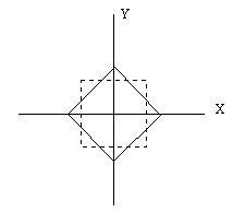
Translation
Translations allow you to place a shape wherever you want to. The following figure attempts to depict the concept.
The dotted lines represent the coordinate system outside the Transform node. The full lines represent the local coordinate system inside a Transform node which defines a translation as specified by the arrow vector. The translation in the figure could be (1,1,0), i.e. the local coordinate system in the Transform node would have has its origin the point (1,1,0) from the coordinate system defined outside the Transform node.
You have probably already guessed that the two figures with a set of cubes had several translations involved.
Composing Multiple Geometric Transformations
Up till now you've been playing with single transformations, but you can combine two or all geometric transformations in a single transform node.The transformations are independent of each other. For instance if you have both a translation and an orientation in the same Transform, the translation is not affected by the orientation and vice-versa.
In the above example if you did want the translation to occur in the rotated axis system then you should define two nested Transform nodes, placing the orientation in the outter Transform, and the translation in the inner Transform node.