
Full list
VRML Interactive Tutorial
Introduction
VRML File Structure
Drawing: Shape node
Geometry Nodes:
|
Box
Sphere Cone Cylinder PointSet IndexedLineSet IndexedFaceSet Extrusion ElevationGrid Example: Chessboard Text FontStyle |
| Material
Textures
Texture Transform |
|
Directional Light
Point Light Spot Light |
Hierarchical Node Structures
|
Group
Transform Collision Anchor Billboard Switch |
Defining and Instancing Nodes
Defining Levels of Detail
Events in VRML
|
Creating Paths between events:
ROUTE
Generating Events based on Timers or User Actions
|
|
Color
Coordinate Normal Orientation Position Scalar Example |
|
Sound
AudioClip |
|
Who Am I: NavigationInfo
Where Am I: ViewPoint |
|
Background
Fog |
| WorldInfo |
|
Coordinate
Color Normal |
TextureCoordinate
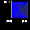
A texture is represented in a 2-D coordinate system (s,t) that ranges from 0 to 1 in both directions.
Syntax:
|
the field point takes a set of 2-D coordinates which define the selected area. The points are separated by spaces.
The ordering of the points is relevant. The order should be counter clockwise starting from the origin to keep the orientation of the texture. If the start point is different then the texture is rotated by multiples of 90 degrees. Presenting the point in a clockwise direction will mirror the texture. Try it yourself of the right frame.
It is now described how TextureCoordinate points define texturing for a single face. Afterwards particular features of textures for IndexedFaceSet and ElevationGrid are presented.
You can select only a part of the texture, for instance if the points given are (0 0) (0.5 0) (0.5 0.5) (0 0.5). Only a quarter of the texture will be used
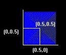
The next figure shows the result obtained.
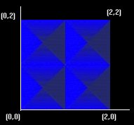
You can also use this node to have the texture repeated, for instance consider the following points: (0 0), (2 0),(2 2), (0 2). In this case the texture is repeated twice in each dimension.
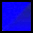
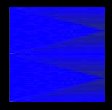
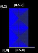
More complex settings can be used which restrict the texture in one dimension but repeat it in the other dimension. For example consider the points (0 0) (0.5 0) (0.5 2) (0 2). The left image shows the result of using this texture coordinates in a square face, the right image shows the area selected in terms os texture coordinates.
In all the examples above the area selected was either square or rectangular. There is nothing preventing you from choosing non-rectangular areas, however the number of points must match the number of coordinates used to build the face, i.e. you can't match a triangular selection into a square face.
The next two sections describe particular features of IndexedFaceSet and ElevationGrid,
IndexedFaceSet
The number of points should match the number of coordinates used to define the face, if multiple faces are defined then the number of points must agree with the number of points used to define each face.
The number of points in the TextureCoordinate must be at least equal to the number of points of the face with highest number of points.
If the field texCoordIndex is not NULL then the values of this field specify the indexes of the TextureCoordinate points which are used to define the selection for each face.
If the field texCoordIndex is NULL then the field coordIndex is used to specify the indexes.
ElevationGrids
When you specify an ElevationGrid you define a grid in which each point of the grid has a height. By default, i.e. if no TextureCoordinate is defined, texturing is controlled by TextureTransform. However sometimes you may want more control in the way textures are applied.
A texture coordinate is defined for each point in the grid. The first point in the grid corresponds to the first point in the TextureCoordinate node, the last point in the grid corresponds to the last point in the TextureCoordinate node. There must be as many points in the ElevationGrid as there are in the TextureCoordinate node.