
Full list
VRML Interactive Tutorial
Introduction
VRML File Structure
Drawing: Shape node
Geometry Nodes:
|
Box
Sphere Cone Cylinder PointSet IndexedLineSet IndexedFaceSet Extrusion ElevationGrid Example: Chessboard Text FontStyle |
| Material
Textures
Texture Transform |
|
Directional Light
Point Light Spot Light |
Hierarchical Node Structures
|
Group
Transform Collision Anchor Billboard Switch |
Defining and Instancing Nodes
Defining Levels of Detail
Events in VRML
|
Creating Paths between events:
ROUTE
Generating Events based on Timers or User Actions
|
|
Color
Coordinate Normal Orientation Position Scalar Example |
|
Sound
AudioClip |
|
Who Am I: NavigationInfo
Where Am I: ViewPoint |
|
Background
Fog |
| WorldInfo |
|
Coordinate
Color Normal |
IndexedLineSet Node
The IndexedLineSet node specifies a set of polylines in the local coordinate system and associated colors.
This node contains five fields: coord, coordIndex, color, colorIndex and colorPerVertex.
The coord field specifies a Coordinate node. In this node a set of 3D coordinates are given.
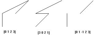
The coordIndex field specifies a list of coordinate indexes defining the polylines to be drawn. To separate the indexes from one polyline a space is used, to separate the sets of indexes from two adjacent polylines the marker -1 is used, i.e. an index of -1 indicates that the current polyline has ended and the next one begins.
The color field defines a Color node. This node defines a list of colors to apply to the polylines. The color is optional, the default values being applied if the field is not specified. If a Material node is specified the default color is the emissive color from this node. Note that both the default emissive color and background are black, so if no color is specified and the default background is used you won't be able to see the lines.
The colorIndex serves the same purpose has the coordIndex but regarding colors.
The colorPerVertex is a boolean field which defines how the colors are applied.
Before presenting the syntax let's see some examples. In all the examples presented, the coord field has the following coordinates: 0 0 0 1 1 0 -1 0 0 -1 -1 0 Playing with coordIndex
Playing with colors: The colors specified are Red, Green and Blue
| colorPerVertex TRUE | colorPerVertex FALSE | |
| colorIndex [0 1 2 0 ] | colorIndex [0 1] | |
| coordIndex [3 0 2 1] | coordIndex [0 1 -1 2 3] |
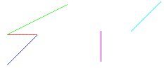
Note: On the example which had colorPerVertex set to TRUE the colors presented for each line are the average color from the two colors defined for the end of each line.
Syntax:
|